Description
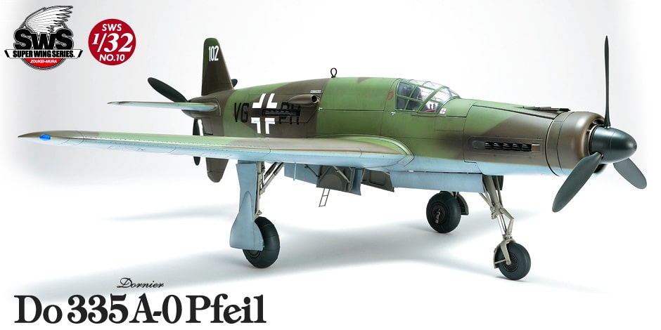
Why make tandem engines with a push-pull layout (serial) instead of the usual twin-engine?
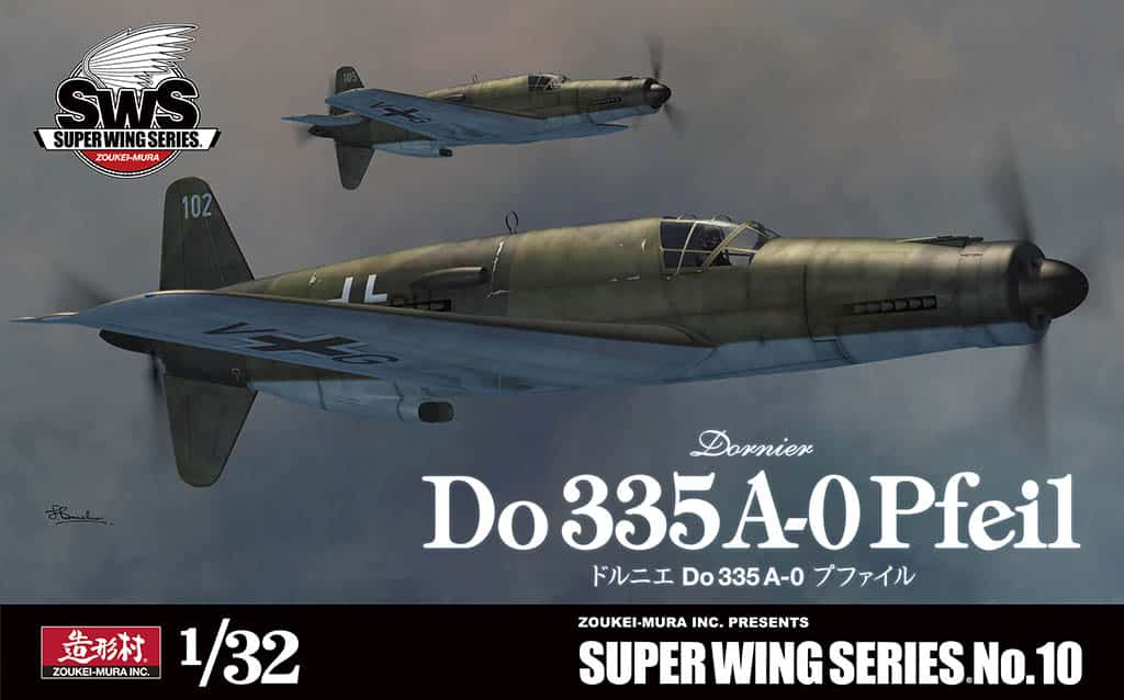
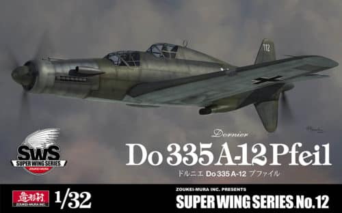
Build our SWS kit and you will understand the curiosity of the Dornier design!
This SWS kit is based on the thoroughly research we made on the only Do 335 real machine still existing at the Smithsonian Museum in the U.S., so we have gone to the core of the Dornier design. The engines installed back and forth give the aircraft a singular shape, and the secret of the fastest reciprocating engine is all in the push-pull layout. Why, as in all other big aircrafts, the twin-engine are not horizontally installed on each of the main wing, but are installed back and forth in the fuselage? The DB 603 engines are installed back and forth while the MK 103 autocannon pass through them. The robust landing gears, the main girder of the box structure supporting the tough main wings etc., all are reproduced. Why is this aircraft having such a particular shape? Why was a machine like this required just at the end of the war when the conflict was intensifying? Build this SWS kit and you will have all the answers. This is it! By this plastic model you can reproduce the real airplane. Enjoy this new world of scale models acclaimed by aircraft fans all over the world.
1. AIRCRAFT SELECTION
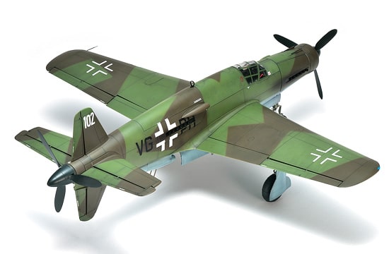
The war situation was deteriorating day by day. Enemy heavy bombers invaded and arrived at the heart of the country without any problem. In order to bring about a miracle to the German Army which was about to be defeated, they had to work out a way to effectively attack the enemy’s strategic sites. Under the circumstances, the Luftwaffe requested a “twin-engine high-speed bomber capable to reach the enemy lines where we don’t own air superiority”. What was the answer from the Dornier Company which had gotten a patent for tandem-mounted engines? The answer was an aircraft which was transformed from a bomber to a multi-role heavy fighter in the development stage. On the robust fuselage the DB 603 A were installed back and forth, making it a high-speed fighter with a phenomenal thrust power, the main girder of the box structure supporting the tough main wings is another particularity of this Luftwaffe double-engine aircraft. Everything is reproduced with this SWS kit.
4. COCKPIT
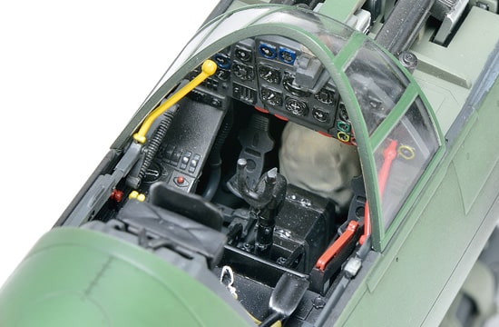
The cockpit of Do 335 is equipped with an ejection seat. The ejection is enabled by pulling the emergency ejection lever. However, in order not to be ejected in the rear propeller, first the canopy and the fuselage need to be uncoupled by the canopy release lever, then the cockpit must be abandoned at the same time with the rear propeller. The ejection of the seat is possible due the air-pressure-moved cylinders placed on the back of the ejections seat. In that situation, the pilot puts his feet on the bar coming out in front of the seat. There is a safety parachute installed on the back of the headrest. After being thrown out in the air, it seems that the pilot fell down with the parachute. The cockpit grip is supposed to be in common with the He 219 and the “Revi 16D” has been adopted as sighting device for the bomber. The left console has the throttle lever and the fuel supply lever; the right console has the bomb release lever and the receiving operation panel of the “FuG 16 ZY”. The SWS will show you every detail of the pilot’s “workplace”.
7. INTERNAL STRUCTURE
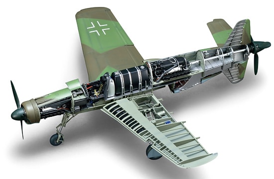
The front engine mount is supposed, from the wielding mark visible up and down, to have had a hollow structure in the middle. In spite of its geometric design, the outer shape is pretty soft. As for the cooling system, the loop radiator installed in the nose is combined with the oil cooler in the upper section. This made the Do 335 look as an air cooled aircraft. The rear engine mount has a double support structure, one in the part connected with the side of the engine, and one in the part connected with the gearbox. The “DB 603E” that was planned to be installed in the A-6 model, had an improved gear housing that made possible to connect it directly to the engine mount, so the ring-shaped coupling used in the “DB 603A” to connect it to the mount, was not necessary. The cooling of the rear engine is due to a radiator put on the low part of the aircraft and an oil cooler put on its back. The radiator duct inhales the air from the base, cooling down the radiator, and sends it to the tail by the air conduction pipes; this structure resembles the one of the American “P-51D”.
2. ENGINE
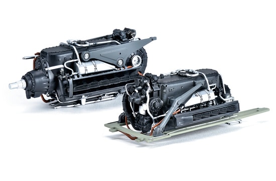
DB 603 liquid-cooled inverted V-type 12 cylinder engine made by Daimler-Benz . Its design was based on DB601 engine which adopted many advanced and complicated systems such as direct injection pump, variable speed supercharger, and many roller bearings. Even though these systems make it difficult to manufacture the aircraft, the company overcame it with high technology and maintained its superiority over the other aircrafts. The engine’s displacement was 44,510cc, take-off power output was 1,750hp/2,450rpm. These engines, installed back and forth in a “push-pull” layout, were the source of the plane’s capacity to reach the enemy lines without air command.
Type: 12-cylinder liquid-cooled inverted V-type engine with supercharger
Bore x Stroke: 162mm×180mm
Displacement: 44.52L
Length: 2,610.5mm
Diameter: 830mm
Supercharger: centrifugal supercharger
Output capacity:
Take-off power: 1,287kw (1,750PS)
Cruising power: 1,111kw (1,510PS)
Compression ratio: 7.5: 1 left block, 7.3: 1 right block
5. LANDING GEAR
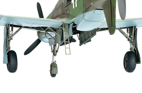
Since there is also a propeller at the rear of the plane, all the three landing gears (nose and main gears) play an important role for the agglutination device of the Do 335. The front gear is foldable on the back thanks to the oil pressure cylinder, and is equipped with a steering device. The frame with its bending pipes and the fender, made solid by the wielded metal sheet are also beautifully represented. Main landing gear is also foldable thanks to the oil pressure cylinder on the side (fuselage central section). An embedded protection is equipped to avoid the split of the main gear cover and, to put away the large main wheel once it has been closed; it is connected to the cabinet door of the swelled gear. The basic shape of this SWS kit has been designed to fix the angulation and the strength of both gears. This way, there will be no doubt about angulation and strength.
8. ARMAMENT
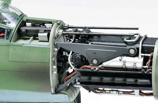
The main weapons of the aircraft are the Mauser’s MG 151/20mm machine guns installed on the upper surface, and the Rheinmetall’s MK 103/30mm cannon that goes through the central section of the engine mount. The cannon is also known as the “Motor Cannon”. The access hatches to every weapon are only on the nose starboard. From there, it is possible to remove the magazine of the MG 151, only on the starboard side, supplying bullets to the MK 103. The discharge spaces of each empty cartridge are concentrated in the central section, and the empty cartridges are kept without being left out until the plane returns to its base. It is thought that the real thing was supposed to be equipped with a propeller in the back section too. There is also a bomb storage near the fuselage central section, because the plane was originally designed to be developed as a “bomber fighter”. As for this kit, since the reproduction is the “A-0” from the first production lot, the warhead is not equipped but the alignment of the inner section structure is a highlight of this kit.
3. PROPELLER
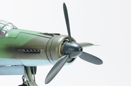
The plane had two VDM propellers—one mounted in front and one at the back. The shapes and diameters of these two propellers are different, so we made more elaborately research on them than usual. The front propeller is a tractor propeller with a diameter of 3.5m. The trailing edge has a flat surface like being cut off. The rear propeller is a pusher propeller with a diameter of 3.3m, and it is directly connected to the engines with an extending shaft. The extending shaft separates in two parts in its middle, the coupling part becoming the gear coupling type, which allows flexibility even if the center axis slips off to some extent due to the torsion of the fuselage. One thinks that by adopting this device, the Luftwaffe wanted to prevent resonance and damage to the aircraft. By the way, in the aircraft manual, the word “luftschraube” (literally “air screw”) is used to describe the propellers.
6. MAIN WING
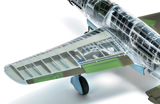
The attachment angle of the robust main wings is 3 degrees. The attack angle from the part between the rib number 14 (placed 3.400mm from the installation point on the fuselage) and the tip of the wing is 1.5 degrees. The twist fall is in between the 3,400mm of space between the fuselage attachment area and the edge, and the angle is also 1,5 degrees. The inclination is designed, based on the rear edge of the main wing. The rear edge is straight. The upper half angle is 6 degrees and is also measured on the rear edge. The sweepback angle of the front edge is 13 degrees; seen from the front, due to the changing shape of the wing and the inclination of outer and inner wings you can see the front edge of the outer wing jumping out. The main wing spar is not a single, stiff spar as in the He 219 or the Fw 190 series, but it relies on the box structure that avoids any involvement of the extended shaft in the back of the fuselage; this is another particular of this aircraft. In the real thing, the box structure is exposed to the upper and lower surface of the main wing and outer panels made up the lower and upper side of the box. In case you just build the inner section of the kit you can enjoy and understand the importance of the box structure as you can also represent the aircraft in a “in production” state.
9. EXTERNAL SHAPE
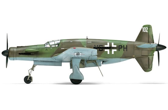
Even if Do 335 is a double-engine aircraft as the He 219, it differs from it because of its stout fuselage, its wall-like thick main wings, and the adoption of the special “push-pull” layout with two engines equipped on the back and forth. Besides, because of the silhouette given by the two vertical tails installed over and under the main wing, the plane was called “Pfeil” and “Arrow” (both having the same meaning). Then, as for the overall side silhouette, the plane was also called “Anteater” and sometimes “Ameisenbar” because of the swell of the fuselage due to the duct of the lower section, the engine in the back of the cockpit and the declining nose. The three gears are all long and bulky; the aircraft itself looks incredibly giant at the time of landing, giving a surprisingly strong impression to the people who saw it. This Do 335, having such a particular look, has been completely reproduced, after investigating the documents concerning the machine kept at the Smithsonian Museum, in accordance to the SWS standards. See the real power the Luftwaffe reached at the end of the World War II!

